- Bez kategorii (21)
- Codes Scratches (4)
DIY touchable desk lamp (touch sensor on/off toggle switch)
Today I want to show you my quick project (about 2h of work): it’s a desk lamp with a touch sensor as toggle (on/off) switch. Wherever you touch the lamp, it will toggle on/off. Take a look at my video below, and you will see what I’m talking about. 😉
How does it work?
The construction contains touch a sensor circuit and switching power supply from an old gsm charger. The whole thing fits perfectly into the bottom part of the lamp, so there is no sign of any modification on the lamp. 😉

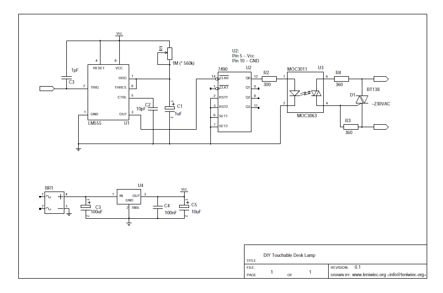
In the above diagram, we can see three parts: a monostable generator built on 555 timer, a frequency divider by 2 and a high voltage output circuit build on triac with optotriac isolation.
A monostable generator is a typical application of the 555 timer. C1 and R1 determine output pulse time, which appears on the U3 output (pin 3), after short pulse from high to low state on trigger input (pin 2 on U1). We can calculate the time of this output pulse using the following formula:
t = ln(3) * R * C = 1.0985 * 560000Ohm * 0,000001F = 0,61516 sIn other words: after a short pulse on TR input the circuit will generate ~0,6s pulse on output (pin 3).
Next, this pulse goes to the input of the ttl 7490 chip, which is configured as a divider by 2. So, every second input pulse triggers high level on Q0 output of U2. And that is how I implemented the toggling on/off.
Further, the signal from Q0 (U2), passes through the current limiting resistor R2 into the U3 optotriac diode. The optotriac U3 isolates our circuit from high voltage 230VAC. The hot side of U3 is connected to the executive D1 triac in a typical way.
On the scheme you may also see a small C3 capacitor, which is connected to the pin 2 (U1). Its function is to “keep” the electrostatic charge from our fingers and make our circuit a little more stable.
On the scheme above there is also a power supply circuit build containing the BR1, U4, C3, C4, C5 elements. I personally skipped it, because I use a power supply from an old gsm charger. But for those who would like to connect their touch sensor to 7…15VAC, there is space for these elements on the PCB.
Start-up
This circuit should work without any problem or beginning tuning. You may only need to tweak the input circuit (around pin 2 of U1) and the generator time by changing R1 and C1, to fit your needs. It is because the size and the location of your sensor determines the size of the static charge etc. In my case I used the whole lamp as one big sensor, and I was forced to add a 10nF and 560k resistor in parallel between pin 2 (U1) and the sensor plate.
Summary
You can find all the files, schemes, the pcb layout and the like in my repository here: https://github.com/leuconoeSH/touchable-desk-lamp
And below there are a few photos of the build…
Enjoy!