- Bez kategorii (21)
- Codes Scratches (4)
8-channel relay card
This project was created as part of my home automatics system. It is a relay card controlled from the PC over a RS-232 port. The card may also be expanded to 5 extra input channels. The project that I describe is a complete solution including hardware with firmware and the software part for PC which consists of linux console utility, php library and java/swing window application.
Hardware
The hardware is typical – MCU, rs232 driver (max232), relay card. Despite the simplicity of the electronic part, I will try to briefly describe it.
On the figure below, you can see the MCU-related part of the card.

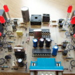
Its main element is a AT90S2313 microcontroller (U1), which is clocked by external crystal at 10,7Mhz (Q1, C1, C2). Moreover there is a rs232 driver MAX232 with related components C3, C4, C5, C6, whose output is derived to male DB9 connector (in this case, we need a null-modem cable to connect it to the PC). The reset pin of U1 is pull-up to +, and port B pins (PB pins), through current limiting resistors (R2..R9), were connected to the relay and the LED control transistors – T1..T8. These transistors work as a common-emitter amplifier (current amplification > 1). The signal is fed from the collectors of these transistors into 8 identical relay blocks that look like in the picture below.

Each block contains a relay with rectifying diode (D9 on the picture above). This diode is used to blot out the pulse induced in the relay coil, which is generated after a sudden disconnection of the relay coil from the power supply. In addition, every relay block contains a LED diode (D1) with a current limiting resistor (R10). The relay contacts are connected in parallel in order to increase the admissible current.

Firmware
The firmware was written in the C language using the avr-gcc compilator and it was uploaded into the device using a USBasp programmer.
The communication procedures, as well as the hardware, are typical, and I can say that this is a “book solution”, and it looks like below.
#define UART_BAUD 9600				/* serial transmission speed */

void UART_putchar(char c)
{
	UDR = c;
	loop_until_bit_is_set(USR, TXC);
	sbi(USR, TXC);
} // end of UART_putchar()

char UART_getchar(void)
{
	loop_until_bit_is_set(USR,RXC);
	cbi(USR,RXC);
	return UDR;
} // end of UART_getchar()

void UART_init()
{
	UBRR = (unsigned char)UART_CONST;		//spped
	UCR = _BV(RXEN)|_BV(TXEN);	//RXEN - permit recive, TXEN - permit send, RXCIE - interrupt on recive
} // end of UART_init()
As we can see in the code above, we have 3 procedures UART_init(), UART_putchar() and UART_getchar(), which are used to: configure, send a character and receive a character. In addition, we have one important constant: UART_BAUD, which determines the transmission speed, and it is set to 9600.
The UART_init() procedure consists of only two lines. In the first line the transmission speed is assigned to the UBRR register, and in the second line, we set RXEN and TXEN bits in UCR register. RXEN and TXEN are respectively responsible for receiving and transmiting data (as You can deduce from their names: RX/TX receive/transmit, EN – enable).
The UART_putchar() procedure takes one parameter, which is a character to send via RS232. This character is assigned to the UDR register and then a loop is executed until the TXC bit is set in the USR register, which means that this character has been sent.
The UART_getchar() procedure is quite similar to the procedure mentioned above, except that this procedure receives the character from uart. The procedure starts and the loop is executed until the RXC bit is set in the USR register, which signifies the arrival of the character, and the last thing of this procedure is to return the received character.
Apart from the uart communication itself, a simple protocol has been implemented in the firmware and it consists of two commands. The first command is used to set the states on the PB port (to turn on and off the relays), and the second one is used to read the current state of the device.
Below there is a fragment of an exemplary session, in which the PK1 and PK6 relays are turned ON, and then the device is queried to return the current state.
s10000100sOK
g10000100
As we can see above, we send to the device a string that contains only 0 and 1 (characters, not integers!), which represents the device outputs. 0 means that the relay is turned off and 1 means that the relay is on. In addition, the 0 and 1 string starts and finishes with a ‘s’ character. In response, the device sends 4 characters: ‘OK\n\r’ if the operation ends with success, and if the operation fails, the device sends a string: ‘Error 2\n\t’ or ‘Error 3\n\r’.
The next line is a query sent to the device for the current state. We send the ‘g’ character and we receive an 8-character long string that contains only 0 and 1, which represent the current states of the device outputs.
To sum up, we can say that we have two commands: the ‘s’ command and the ‘g’ command (set, get), and if we send some other characters, the device will return the error message: ‘Error 0\n\t’. And this is all, I think it’s quite simple 😉
Software
From the PC side, I prepared 3 different applications: a linux console utility, a window Java/Swing application and a php class which allows the manipulation of the device from the www level – this solution is based on the ser2net linux package as a proxy.
Linux console utilities
This application allows to manipulate the device outputs and read their current states from the linux console level. I personally used this app in my cron scripts.
The options available in this program are as follows:
$ ./io_card
Usage: ./io_card -p port [-s (8bit data)] [-g] [-1..8 (on|off)]
-p 	path to the port e.g. /dev/ttyS0 or /dev/ttyUSB0
-s	set output, as parameter we give an 8-character long string that contains 0 and 1
-g	get current device state, it returns an 8-character long string
-1..8	set or clear output from 1 to 8. As a parameter we can give 'on' or 'off'
For example, in order to turn on the relays no. 4 and 6 we can do sth like this:
$ ./io_card -p /dev/ttyUSB0 -s00010100
OK
or we can do this like this:
$ ./io_card -p /dev/ttyUSB0 -4 on -6 on

OK
now, for the current device state we put sth like this:
$ ./io_card -p /dev/ttyUSB0 -g
00010100
next, in order to turn off the relay no. 4 and turn on the relays no. 1 and 2, we can do sth like this:
$ ./io_card -p /dev/ttyUSB0 -4 off -1 on -2 on
OK
The attachment, below this article, contains this application with the source code.
ser2net and PHP
In order to use this solution we need to install and configure the ser2net package. I chose this method of communication with the serial port from the php level, because I believe it is the most universal one. Having properly configured the ser2net, we can draw our device on some public address and control it remotely from some other client application.
So, in order to install the ser2net package in ubuntu, we need to execute these commands:
sudo apt-get install ser2net
After this, the package is downloaded and installed. And then we can start configuring it.
In /etc/ser2net.conf file, you should add the line as below:
localhost,3000:telnet:600:/dev/ttyUSB0:9600 8DATABITS NONE 1STOPBIT
We can read this file as: draw port /dev/ttyUSB0 on port 3000 at the localhost address, set the transmission speed to 9600, 8 bit data, 1 bit stop, no device flow control.
Changing this line, you can customize the ser2net for your own purposes.
After saving this file, we need to restart the ser2net daemon, we can do this with the following command:
sudo /etc/init.d/ser2net restart
After this, we have our port (/dev/ttyUSB0 in this example) drawn on the localhost:3000, so we can move further to have fun with php.
The attachment, below this article, contains the IoCart php class with the following interface:
- IoCart::__construct($strHost, $strPort) – constructor, as the parameters we should give host and port on which ser2net listens.
- IoCart::close() – close the connection
- IoCart::getStatus() – get current device state, the return value is an 8-character long string that contains only 0 and 1.
- IoCart::checkStatus($intPortNumber) – check state of one selected port – $intPorNumber, return value is boolean true or false.
- IoCart::setPort($intPort, $bolState) – set or clear one selected port, $intPort – port number – integer from 1 to 8, $bolState – boolean value: on or off
- IoCart::set($strByte) – set all ports state at once, as parameter we should give an 8-character long string that contains only 0 and 1 characters.
Below there is a screenshot and an exemplary source code of the working script (also included in the attachment).

<?php
 include "IoCart.php";
 $objCard = new IoCart('localhost',3000);

 if(isset($_POST['change']) && $_POST['change']=='1' && isset($_POST['value']) && isset($_POST['port']))
 {
    $objCard->setPort($_POST['port'], $_POST['value']=='1' ? true : false);
 }

?><!DOCTYPE html PUBLIC "-//W3C//DTD XHTML 1.0 Strict//EN"
                      "http://www.w3.org/TR/xhtml1/DTD/xhtml1-strict.dtd">
<html xmlns="http://www.w3.org/1999/xhtml" xml:lang="pl" lang="pl">
 <head>
    <title>8 bit IO Card Example</title>
    <meta http-equiv="Content-Type" content="text/html; charset=utf-8"/>
 </head>
<body>
    <table border="1" align="center" cellpadding="15">
        <tr>
<?php
 $strStatus = $objCard->getStatus();
 for($intI=0; $intI < 8; $intI++):
?>
            <td>Port <?= ($intI+1).': '.($strStatus[$intI]=='1' ? 'On' : 'Off') ?></td>
<?php endfor; ?>
        </tr>
        <tr>
<?php
 for($intI=0; $intI < 8; $intI++):
?>
            <td align="center">
                <form action="" method="post">
                    <input type="hidden" name="port" value="<?= $intI+1?>" />
                    <input type="hidden" name="value" value="<?= ($strStatus[$intI]=='1' ? '0' : '1') ?>" />
                    <input type="hidden" name="change" value="1" />
                    <input type="submit" value="<?= ($strStatus[$intI]=='1' ? 'Off' : 'On') ?>" />
                </form>
            </td>
<?php endfor; ?>
        </tr>
    </table>
</body>
</html>
Window application
And in the end something that adds a little spice.. the window java application. You will find the compiled version included in the attachment, as well.

JAs I already mentioned, it is based on Java/Swing, and is using the RXTXcomm library for communication. This library is also included in the attachment zip in lib directory, it also contains .so and .dll version. Unfortunately, I haven’t tested it on windows box, but… it should work! 😉
I don’t provide the full source code of this, because except of the SerialHandler class, the rest is only GUI and anyone who knows java can do it on their own, according to their own needs and purposes.
Final remarks
Of course in this mini-project, there are a few shortcomings which I am aware of. But everything works fine for me 😉
If you are interested in buying such device as kit or ready-to-use device or if you want to obtain some additional information about this project, feel free to contact me.
Attachments
- main.hex – MCU binary
- board_v2.ps – PCB (PostScript)
- board_v2_mirror.ps – PCB – mirrored view (PostScript)
- IO_Karta.zip – all files in zip archive, pcb, schematic, sources and binarys.