

- Bez kategorii (21)
- Codes Scratches (4)
Rotary shaft encoder: how to connect it and handle it with AVR (ATmega8/16/32/168/328)
Some time ago I wrote an article about using a rotary shaft encoder (Budujemy cyfrowy zasilacz – enkoder obrotowy w praktyce – sorry only polish version), but it was a very specific situation, in other words it wasn’t a very correct way there. So I decided to write, once again, about encoders and try to explain how to connect and handle it, in a correct way, with avr mcu (in the examples I am using ATmega8A-PU, but it should work on any other eg. ATmega32 or arduino compatible ATmega168/328).
Back to theory
As I wrote in the previous article about encoders, rotary encoders have two outputs, let’s name them A and B. When we rotate the knob, on the A and B outputs, we get phase shifted square wave signal. This signal is nothing but a 2 bit Gray code. In the image below I draw it in a more readable form.
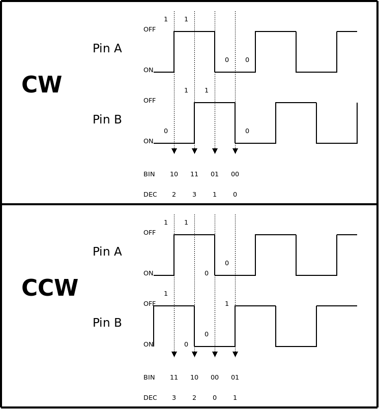
As we can see in the image, if the encoder is rotated in a clockwise direction, then the gray code on the outputs is in the following order: 2->3->1->0->2 and so on. If we start to rotate now in the counter-clockwise direction, we will get the following sequence of gray code on the output: 3->2->0->1. As we know this sequence, we can determine the rotation direction of the knob. This is one of the two methods for reading the encoder’s direction.
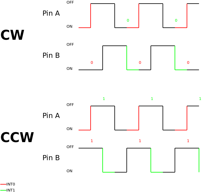
The second method is based on detecting falling edge of the output signal, on one of the output, and checking the current state on another output.

This method has one very important problem. We lost half of the rotary encoder precision, because we detect only every second signal edge. This can be fixed by connecting a second encoder output to another interrupt in the processor and detect the opposite edge of the signal. So if we detect a falling edge on output A, we need to detect a rising edge on output B.
By doing this, we restored our full precision, but we lost two interrupts in our mcu. Typically, we don’t need so much precision, and the first solution with using only one interrupt on mcu is good enough.
Connecting to micro-controller
If you are using an expensive optical encoder, this paragraph is not very important, because this type of encoders provide a very clean signal on its outputs, and there is no need to filter it or debounce. Unfortunately, when we are using cheap mechanical encoders the situation is very different. The internal contacts of these little bastards generate lots of gigs and noises, and when we exceed its maximum parameters, which can be very bad, (eg. maximum rotation speed), we start to get random signals on it outputs.
When I connect one of this dudes to mcu, I always use hardware defined debouncing, I do this because software debouncing can be very difficult and depends on some parameters, such as current shaft speed etc. My debouncing is a simple low-pass RC filter, like shown in the image below.

In the scheme above, the resistor and the capacitor that is connected in parallel create a low-pass filter, with cut-off frequency calculated with this formula: fg = 1 / 2*pi*R*C. So if we use the values from the scheme, we will get:
fg = 1 / 2*3.1415*10000*0.0000001 ~= 159.2HzInterrupts based solution (example based on ATmega8)
The first example is the solution based on interrupts, in which we detect a falling and/or rising edge, and depending on the current state on the second pin we determine the shaft direction.
If we connect our A and B encoder outputs to PD2 and PD3 micro-controller pins, we need to set PD2 and PD3 as inputs:
/* set PD2 and PD3 as input */
  DDRD &=~ (1 << PD2);				/* PD2 and PD3 as input */
  DDRD &=~ (1 << PD3);
  PORTD |= (1 << PD3)|(1 << PD2);   /* PD2 and PD3 pull-up enabled   */
then, we turn on the interrupts’ handler. In order to do this, we need to write the following bits to register GICR and MCUCR:
GICR |= (1<<INT0)|(1<<INT1);	// enable INT0 and INT1
MCUCR |= (1<<ISC01)|(1<<ISC11)|(1<<ISC10); // INT0 - falling edge, INT1 - raising edge
and we also need to enable interrupts:
   /* enable interrupts */
  sei();
Now we need to write some code in our interrupts handlers:
//INT0 interrupt
ISR(INT0_vect )
{
	if(!bit_is_clear(PIND, PD3))
	{
		UART_putchar(*PSTR("+"));
	}
	else
	{
		UART_putchar(*PSTR("-"));
	}
}

//INT1 interrupt
ISR(INT1_vect )
{
	if(!bit_is_clear(PIND, PD2))
	{
		UART_putchar(*PSTR("+"));
	}
	else
	{
		UART_putchar(*PSTR("-"));
	}
}
The Code for INT0 and INT1 handler is very similar. After an interrupt occurs, we check the state of the second input and this determines the current shaft direction. In the example above, if the shaft of the encoder was rotated in a clockwise direction, it is sent using UART “+” character, if not, the “-” character is sent. If we remove one interrupt (INT0 or INT1 – it doesn’t meter), the following code will be still functional, but we will get half of the encoder precision. The whole code looks like this:
#define F_CPU 8000000
#define UART_BAUD 9600				/* serial transmission speed */
#define UART_CONST F_CPU/16/UART_BAUD-1

#include <stdio.h>
#include <avr/io.h>
#include <util/delay.h>
#include <avr/pgmspace.h>
#include <avr/interrupt.h>

#include "uart.h"

//INT0 interrupt
ISR(INT0_vect )
{
	if(!bit_is_clear(PIND, PD3))
	{
		UART_putchar(*PSTR("+"));
	}
	else
	{
		UART_putchar(*PSTR("-"));
	}
}

//INT1 interrupt
ISR(INT1_vect )
{
	if(!bit_is_clear(PIND, PD2))
	{
		UART_putchar(*PSTR("+"));
	}
	else
	{
		UART_putchar(*PSTR("-"));
	}
}

int main(void)
{
  /* init uart */
  UART_init(UART_CONST);

  /* set PD2 and PD3 as input */
  DDRD &=~ (1 << PD2);				/* PD2 and PD3 as input */
  DDRD &=~ (1 << PD3);
  PORTD |= (1 << PD3)|(1 << PD2);   /* PD2 and PD3 pull-up enabled   */

  GICR |= (1<<INT0)|(1<<INT1);		/* enable INT0 and INT1 */
  MCUCR |= (1<<ISC01)|(1<<ISC11)|(1<<ISC10); /* INT0 - falling edge, INT1 - reising edge */

  /* enable interrupts */
  sei();


   while(1)
   {
	//do nothing ;)
	_delay_ms(1);
   }

  return 0;
}
This example and all the corresponding files (makefile, source and headers), are freely available in my repository on github here: https://github.com/leuconoeSH/avr-examples/tree/master/rotary-encoder/interrupt. The repository also includes the procedures to handle UART transmission.
Gray’s code method
The second method is using Gray code. In this case, we don’t need any interrupts at all.
Let’s start from the procedure that will change the two states on A and B inputs (pin PD2 and pin PD3) into 2bit binary value, where the value from PD2 will be the first oldest bit, and the value from PD3 will be the zero oldest bit.
uint8_t read_gray_code_from_encoder(void )
{
 uint8_t val=0;

  if(!bit_is_clear(PIND, PD2))
	val |= (1<<1);

  if(!bit_is_clear(PIND, PD3))
	val |= (1<<0);

  return val;
}
In the code above, we have declared 8bit unsigned integer variable, whose start value is 0 (00000000b), then we check if there is a high logical state on pin PD2, and if there is, we put binary 1 on the bit, which is first from the right side. So we get this value: 00000010b. Then we do the same thing with the second input pin PD3, the only difference being: now we set the value on 0 position. By doing this, we get 2bit Gray code, which is corresponding to the states on PD2 and PD3 inputs, in val variable. This value can be equal to 0 (00b), 1 (01b), 2(10b) or 3 (11b).
Then, we only need to write this value as a start value, and check if any new value fits into the 2->3->1->0 sequence or the 3->2->0->1 sequence, and after that we will know in which direction the shaft of our encoder was twisted.
  /* ready start value */
  val = read_gray_code_from_encoder();

   while(1)
   {
	   val_tmp = read_gray_code_from_encoder();

	   if(val != val_tmp)
	   {
		   if( /*(val==2 && val_tmp==3) ||*/
			   (val==3 && val_tmp==1) ||
			   /*(val==1 && val_tmp==0) ||*/
			   (val==0 && val_tmp==2)
			 )
		   {
				UART_putchar(*PSTR("+"));
		   }
		   else if( /*(val==3 && val_tmp==2) ||*/
			   (val==2 && val_tmp==0) ||
			   /*(val==0 && val_tmp==1) ||*/
			   (val==1 && val_tmp==3)
			 )
		   {
				UART_putchar(*PSTR("-"));
		   }

		   val = val_tmp;
	   }

	   _delay_ms(1);
   }
In the code above, the sequences: 2->3, 1->0, 3->2 and 0->1 were commented, because they are corresponding to the transition state of the encoder, and if we had left them uncommented, then every single encoder ‘click’ would generate two impulses.
If we don’t want to include the encoder procedures in our main program loop, we can use an internal timer/counter to run this procedure in the interrupt every time the counter overflows.
The whole code can look like this:
#define F_CPU 8000000						/* crystal f				 */
#define UART_BAUD 9600						/* serial transmission speed */
#define UART_CONST F_CPU/16/UART_BAUD-1

#include <stdio.h>
#include <avr/io.h>
#include <util/delay.h>
#include <avr/pgmspace.h>
#include <avr/interrupt.h>
#include "uart.h"

uint8_t read_gray_code_from_encoder(void )
{
 uint8_t val=0;

  if(!bit_is_clear(PIND, PD2))
	val |= (1<<1);

  if(!bit_is_clear(PIND, PD3))
	val |= (1<<0);

  return val;
}

int main(void)
{
  uint8_t val=0, val_tmp =0;

  /* init UART */
  UART_init(UART_CONST);

  /* set PD2 and PD3 as input */
  DDRD &=~ (1 << PD2);				/* PD2 and PD3 as input */
  DDRD &=~ (1 << PD3);
  PORTD |= (1 << PD3)|(1 << PD2);   /* PD2 and PD3 pull-up enabled   */

  /* ready start value */
  val = read_gray_code_from_encoder();

   while(1)
   {
	   val_tmp = read_gray_code_from_encoder();

	   if(val != val_tmp)
	   {
		   if( /*(val==2 && val_tmp==3) ||*/
			   (val==3 && val_tmp==1) ||
			   /*(val==1 && val_tmp==0) ||*/
			   (val==0 && val_tmp==2)
			 )
		   {
				UART_putchar(*PSTR("+"));
		   }
		   else if( /*(val==3 && val_tmp==2) ||*/
			   (val==2 && val_tmp==0) ||
			   /*(val==0 && val_tmp==1) ||*/
			   (val==1 && val_tmp==3)
			 )
		   {
				UART_putchar(*PSTR("-"));
		   }

		   val = val_tmp;
	   }

	   _delay_ms(1);
   }

  return 0;
}
All codes (including makefile, source file and headers) as well as uart.h and the corresponding uart.c, can be found in my GitHUB repository here: https://github.com/leuconoeSH/avr-examples/tree/master/rotary-encoder/normal.
Summary
As you can see, handling a rotary shaft encoder is really simple, and the biggest pain is the quality of the encoder itself and its debouncing. The solution is to use an optical encoder, but it is a very very expensive solution. 😉 For example, an optical encoder can cost around 100Eur (~140USD), when the el cheapo mechanical one, costs only a few cents.
So there’s nothing left other than wishing you, my dear readers, many successful experiments and projects with your encoders! 🙂
Enjoy!
… [Trackback]
[…] Read More to that Topic: leniwiec.org/en/2014/04/28/rotary-shaft-encoder-how-to-connect-it-and-handle-it-with-avr-atmega8-16-32-168-328/ […]