- Bez kategorii (21)
- Codes Scratches (4)
Numeric keypad with serial or SPI interface
Today I would like to show and describe you my keypad with serial interface mini project which we can directly connect to mcu UART (for me it was Atmega8 and Atmega32, but you can connect it with any other chip with build-in uart).

How does it work?
It is a typical numeric keypad with keys from 0 to 9 + 4 extra function keys (a,b,c,d), power supply of 5 volts dc, serial data output (9600 boud rate) or spi interface. The switches are electrically connected into a matrix, for mcu pin resources saving. All the switches in a given column are connected together and all in a given row also. Below you can see the scheme of that connection:

Later on, the firmware inside the micro-controller (I used for this purpose atmel AT90S2313 chip, but you can use whatever you like as long as you are familiar with its coding) “scans” that matrix in search of the shorted contacts. It is done as follows:
The rows from top to bottom are connected to PD6, PB0, PB1 and PB7 pins of the micro-controller and the columns are connected to the pins PB6, PB5, PB4, PB3, PB2, which you can see in the image above. First of all, the pins which are connected into rows, are set as outputs:
	DDRB |= (1<<PB0); //port as output
	DDRB |= (1<<PB1); //port as output
	DDRB |= (1<<PB7); //port as output
	DDRD |= (1<<PD6); //port as output
and the ones connected to the columns as inputs:
	DDRB &=~ (1 << PB2); //port as input
	DDRB &=~ (1 << PB3); //port as input
	DDRB &=~ (1 << PB4); //port as input
	DDRB &=~ (1 << PB5); //port as input
	DDRB &=~ (1 << PB6); //port as input
with enabled internal pull-up resistors:
	PORTB |= (1 << PB2); //pull-up enable
	PORTB |= (1 << PB3); //pull-up enable
	PORTB |= (1 << PB4); //pull-up enable
	PORTB |= (1 << PB5); //pull-up enable
	PORTB |= (1 << PB6); //pull-up enable
and all the ports configured as outputs are set in high logic state.
Then, from top to bottom the micro-controller gives low logic state to the next rows until the last row is reached.
After giving the high state to the first row, the program checks one by one from left to right, if any of the buttons are pressed down, i.e. if they generate low state on one of the inputs connected to the columns. If one of the inputs is in low state, it means that the button has been pressed, so the program starts to read the current position (the number of the column and the row) and this way it can determine which button has been pressed. If in a given column none of the buttons has been pressed, the program continues to search until it reaches the last column and the last row, and after that it starts from the beginning. Below you can see the animation which illustrates how this algorithm works.

After the software detects that a button is pressed, it runs a simple code which debounce input signal from the switch, and then the character corresponding to the button is sent by the serial port.
The support for the serial port is typical and the port is configured in transmit only mode. Step by step it looks like this in the code:
#define F_CPU 8000000L
Here we define the mcu oscillator frequency, and then we define the expected uart boud rate:
#define UART_BAUD 9600
and we also create a simple macro, which will be used to calculate the constance value needed by the micro-controller to handle the serial transmission.
#define UART_CONST (F_CPU/(16ul*UART_BAUD)-1)
we write the value calculated by this macro into the UBRR register, and by this we configure the transmission speed
UBRR = (unsigned char)UART_CONST;
then, we use the UCR register, in which we set the TXEN (TX Enable) bit, which means the approval for transmitting the characters (analogically to this one, there is also the RXEN bit for receiving data).
After these operations we have a well configured serial interface with speed set to 9600.
Now it’s the time to send some data into it! To do this, we have created a procedure UART_putchar(), which looks like this:
void UART_putchar(char c)
{
    UDR=c;
    loop_until_bit_is_set(USR,TXC);
    USR |= (1<<TXC);
}//end of UART_putchar()
The UDR register is a serial port input register – its content will be sent to the serial port, and after this is done successfully (the transmission is finished), the TXC bit in the USR register will be set. After successful transmission we can clear this bit (the last line of the above procedure), allowing this way to send the next character via serial interface.
If you use a serial port interface in your micro-controller based project, you need to be careful when choosing the quartz, which is used by the mcu oscillator. This is important because with a different crystal frequency, we will get a different percentage value of the error in transmission. And this value can be from zero percent to a few percent. In the table below you can see this dependence (this table comes from atmega8 data-sheet) .

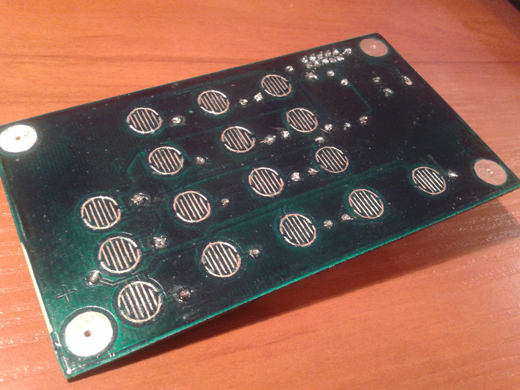
Construction
I made my prototype keypad on a double layer FR4 (glass-epoxy) pcb, tracks were created using the thermotransfer method (greetings for my laminator ;), and it is all secured by a thermosetting solder mask.
The buttons were taken from the ActiveJet ASC-8003 calculator (it costs around 1eur). In this particular calculator we have a fancy lcd display, with big and easily readable numbers, which I think I will hack and describe soon.
Images, movies , files, madness!
Below you can see the movie in which you can take a look at my working keypad prototype. In this movie it is connected to pc with a USB->RS232 cable with TTL levelled outputs, on which gtkterm is running.
Below you will find the project files that you may download and the photo gallery, have fun!